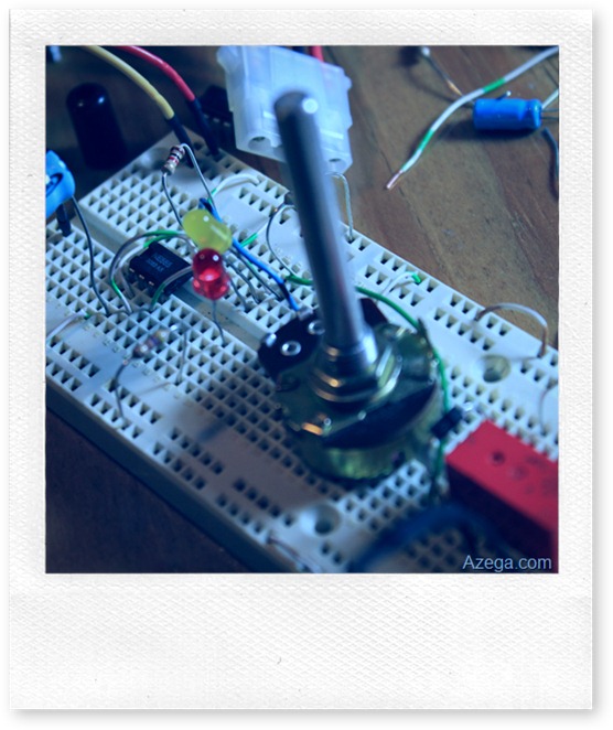
 This is my entry for the 555 Contest recently started by Jeri Ellsworth and Chris Gammell. It is a camera timer (aka. intervalometer) for taking time lapse videos with my DSLR. It is a very simple circuit designed around a 555 timer IC. It has indicator LEDs, a relay to control the camera, and a potentiometer which allows me to set the photo interval between 15 seconds down to around 1 second.
I’ll admit that it’s not much to look at, but that is because I threw it together in a couple of hours from parts I had laying on my workbench. I designed, built, troubleshot, and did a test run in one short evening. I have wanted to experiment with time lapse photography for a while now, and this seemed like a good opportunity to give it a go. I’ve got some other projects related to time lapse and general photography in the works, so click the subscribe button so you can be notified when they’re available.
Design:
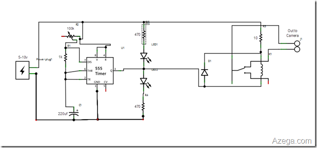
At it’s core, it’s just a basic astable oscillator. The output is connected to a relay which closes the contacts to the camera remote. I used a relay to isolate the camera electronics from the circuit and so I wouldn’t have to worry about what voltages were required by the camera. I also added a snubber diode to the coil side of the relay to arrest the voltage spike when the relay turns off.
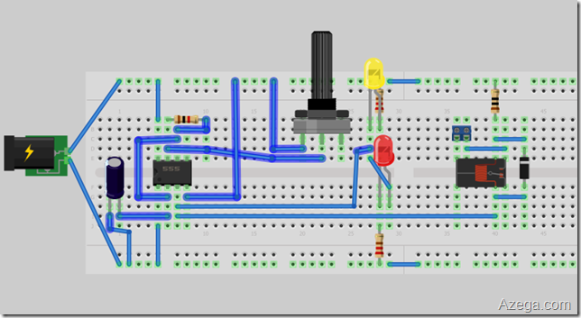
And Here is basically how it was laid out on the breadboard.
Connections:
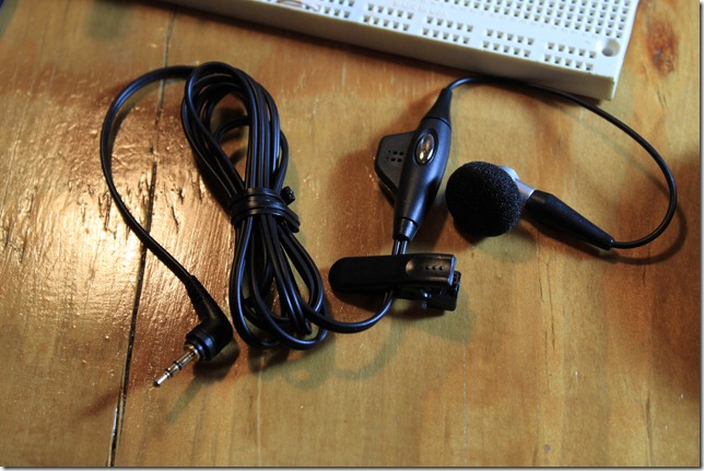
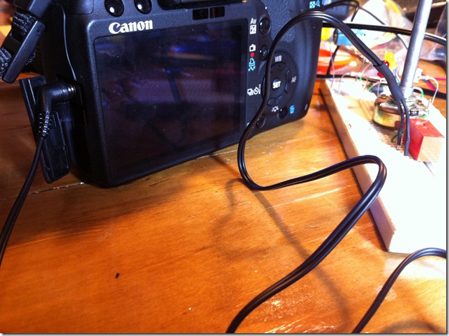
I hacked an old cell phone remote for the connector to plug into my camera. For power, I used an old 7.5 volt wall wart.
Testing:
Here is the initial test showing the oscillations. This is before I had it hooked up to the relay and camera.
Trial Run:
Here is the first complete trial. I set it to take a picture every 5 seconds, then used Sony Vegas HD to compile them into a 15 fps video.
I was originally going to build this circuit using an arduino, but I wanted to do something for the 555 contest, so I thought this would be a good application. I like this circuit so much and the parts are so cheap, I’m going to rework it to add a few features and build it more permanently on a circuit board and put it in a case, so check back for that.
Let me know what you think in the comments section below.
Update:
(everything below this point was added after the close of the contest)
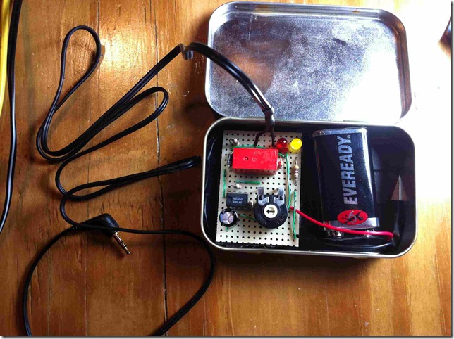
I created a more permanent version by soldering it onto a protoboard that fits inside an altoids tin and also changed the power source to a 9v battery to make it more portable. Other changes include changing the size of the capacitor to 470 uf adding a 470 ohm resistor in series with the potentiometer to set the minimum interval to about 1 second. Previously, if you turned the pot all the way down, it would just stop oscillating and it made it hard to set times shorter than a couple of seconds. Now, the range is from about 1 second to around 30 seconds.
What I want to do now is to measure the current being drawn by the relay and see if I can adjust the current limiting resistor so the battery lasts longer. I also want to look into using an opto-isolator or a solid state relay to eliminate the relay and lower the overall power consumption.
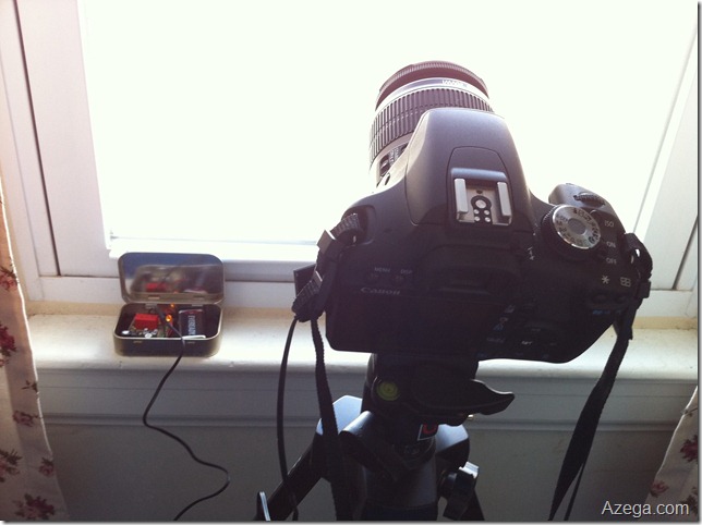
Here is a test of the new design and a better video.
Here are some tips for capturing time lapse video:
Set your camera to manual mode. Manual mode will let you lock down the exposure, aperture, ISO, white balance, etc. You don’t want your camera to reevaluate the scene in the middle of the video and give you an inconsistent look. I usually take a few shots in aperture priority mode to figure out what the best settings will be.
Set the focus manually. If you leave it in auto focus mode, it will try to refocus on the scene every time it takes a shot. This will make it use up your battery faster, take longer to take shots, and the focus will keep changing in your final video.
Take more frames for smoother video. Both videos above were captured at about one frame every 5 seconds. The difference is that the first video was rendered at 15 fps and the second one was rendered at 30 fps and I think it is more smooth.

Nice project and writeup! I think my favorites in this contest are the ones that are simple but interesting applications. It’s fun to watch the stop motion traffic.
Hey, I just built this fantastic circuit and it works perfectly! I can’t wait to try it out! Unfortunately, the Olympus E-510 needs the relay to be closed for a bit longer. I’m just getting to know 555s and I’m not entirely sure how to slow down the output cycle. Can you offer any suggestions? I have some ideas, like adding a second resistor between pin 7 and the capacitor with a diode in parallel, but I haven’t sorted it all out yet.
Any help you can offer would be greatly appreciated! Thanks again for the awesome circuit!
Txoof, you can change the value of the 1k resistor (between pin 7 and the capacitor) to adjust the on time. The formula for determining the on time is t=0.69*R*C. In my example above that would be 0.69*1000*.00022 which works out to about 152 milliseconds. If you replace the 1k resistor with a 4.7k that would give you an on time of about 3/4 of a second. You could also increase the size of the capacitor. The values I used were based on what I had laying around.
My intervalometer results:
http://www.txoof.com/2011/04/time-lapse-intervalometers-and-555.html
What kind(specs)of relay is required ?
Also, I am worried about hurting the camera because we don’t know what voltage levels would be appropriate.
One more question. Whats the actual need for relay here ? Cant we directly give the Output to camera ?
thanks,
Piyush
I don’t know the exact specs of the relay I used. It’s just a little relay I had pulled out of some other equipment a long time ago. It doesn’t require much, we’re only talking about 5-10 volts and less than one amp (probably just a few milliamps, though I haven’t measured it).
The reason for using a relay is so you don’t have to worry about what voltage the camera uses. As far as the camera knows, it’s just a switch, just like any other remote switch. You could wire the output of the 555 circuit directly to the camera if you wanted to figure out what voltage was required, but then it would only work on that camera and maybe not on any others.
Thanks for the questions.
I’ve got a 500k potentiometer, will that work?
Humxa,
Yes, you can use a 500k pot, but it will change the range of frequencies you will be able to set it to.
You might try using a smaller capacitor to offset this.
N-chanel mosfet instead of relay?
I have made it exactly like you have but when the green led blinks the relay switches but dosen’t go back to its original state. What am I doing wrong?